Research Article | | Peer-Reviewed

Front Surface Field (FSF) Layer Thickness Engineering in Heterojunction Solar Cells: Efficiency Optimization Through Predictive SILVACO-TCAD Simulation

Received: 29 June 2025     Accepted: 8 July 2025     Published: 28 July 2025
Views:       Downloads:
Abstract

This study focuses on optimizing the thickness, doping, and bandgap energy of the Front Surface Field (FSF) layer in silicon heterojunction (SHJ) solar cells using predictive simulation with SILVACO-TCAD. SHJ solar cells are known for their high efficiency, low-cost manufacturing, and low-temperature fabrication processes. The FSF layer, typically composed of p+-doped hydrogenated amorphous silicon (a-Si:H), plays a pivotal role in determining cell performance. Key Methodology: The research employs the TCAD-SILVACO Atlas simulation software to model SHJ solar cells and analyze the influence of FSF layer parameters on photovoltaic performance, particularly the open-circuit voltage (VOC), short-circuit current density (JSC), fill factor (FF), and overall efficiency (η). The simulation integrates the Poisson and continuity equations, Boltzmann statistics, and models for Auger and Shockley-Read-Hall (SRH) recombination. Major Findings: FSF Thickness: Optimal efficiency (~23.5%) is achieved with an FSF thickness around 5 nm. Increasing the thickness beyond this value leads to reduced VOC and FF due to enhanced recombination and increased resistivity. Doping Concentration: Higher doping levels in the FSF layer strengthen the electric field at the junction, improving carrier separation and collection. However, excessive doping can cause additional recombination, emphasizing the need for balanced optimization. Bandgap Energy: A lower bandgap enhances photon absorption but increases thermal losses, while a higher bandgap limits absorption but can theoretically improve VOC. An optimal bandgap value around 1.7 eV, combined with a 5-7 nm thickness, was identified for peak efficiency. Simulation Stability: The study temporarily replaced the conventional indium tin oxide (ITO) front layer with silicon dioxide (SiO2) for simulation stability. This substitution was for numerical purposes only and is not applicable in real-world fabrication. The research highlights that achieving high-efficiency heterojunction solar cells requires precise, simultaneous optimization of the FSF layer's thickness, doping concentration, and bandgap energy. The study confirms that a careful balance of these parameters minimizes recombination losses, optimizes charge transport, and enhances photovoltaic performance. Future work should involve further experimental validation and the integration of more realistic front contact materials such as transparent conductive oxides (TCOs).

Published in Advances in Materials (Volume 14, Issue 3)
DOI 10.11648/j.am.20251403.11
Page(s) 65-79
Creative Commons

This is an Open Access article, distributed under the terms of the Creative Commons Attribution 4.0 International License (http://creativecommons.org/licenses/by/4.0/), which permits unrestricted use, distribution and reproduction in any medium or format, provided the original work is properly cited.

Copyright

Copyright © The Author(s), 2025. Published by Science Publishing Group

Keywords

Heterojunction Solar Cells, SILVACO-TCAD Simulation, Front Surface Field (FSF), Photovoltaic Efficiency, Doping Optimization, Band Gap Engineering

1. Introduction
Silicon heterojunction (SHJ) photovoltaic (PV) cells, based on a p+-a-Si:H / n-c-Si / n+-a-Si:H structure, are among the most promising technologies in the photovoltaic sector. They attract strong interest due to their low manufacturing cost, low-temperature processing, favorable absorption properties of hydrogenated amorphous silicon (a-Si:H), and the mature technological control of crystalline silicon.
According to Jan Haschke et al. (2018), SHJ solar cells have achieved efficiencies exceeding 25%, driven by significant progress in fabrication techniques and active layer design . However, their overall performance remains highly dependent on the characteristics of the front surface field (FSF) layer, typically made of p+-doped a-Si:H.
A detailed investigation of the FSF layer’s geometric, electrical, and optical parameters is therefore crucial for efficiency optimization. In this study, we use TCAD-SILVACO numerical simulations to assess how variations in the FSF layer’s thickness, doping concentration, and optoelectronic properties influence the key photovoltaic performance indicators.
2. Electrical Modeling and Simulation of a Solar Cell
2.1. Modeling
The operation of a photovoltaic (PV) solar cell can be represented using an equivalent electrical circuit (see Figure 1). In this model, the cell is considered as a current generator. The current source IPh represents the photogenerated current under light irradiation. Two diodes, D1 and D2, respectively model the generation-recombination phenomena in the space-charge region and the diffusion current of carriers in the neutral regions.
The equivalent circuit also includes:
1) A series resistance RS, which accounts for internal ohmic losses within the cell (notably at the metallic contacts, the emitter, and the substrate);
2) A parallel resistance RP (or shunt resistance), which models leakage currents due to crystalline defects, impurities, or edge effects within the cell, particularly in the bulk or near the junction .
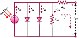
Figure 1. Representation of a Photovoltaic Solar Cell .
By applying Kirchhoff’s laws to the equivalent circuit shown in Figure 1, the current I delivered by the cell can be expressed as the algebraic sum of the different currents flowing through the circuit:
I=Iph-ID1-ID2-ISh(1)
Where:
I: Output current.
Iph: Photocurrent.
ID1: Generation/recombination current in the space charge region (SCR).
ID2: Diffusion current in the quasi-neutral regions.
Ip: Resistive loss current.
The diode current is expressed as:
ID=I0expqV+IRSnKT-1(2)
The shunt current is expressed as:
Ip=V+IRSRp(3)
The total current becomes:
I=Iph-J01expqV+IRSKT-1-J02expqV+IRS2KT-1-V+RSIRP (4)
Where:
J01: Saturation current density of diode D1 related to carrier diffusion in the quasi-neutral regions of the base and emitter.
J02: Saturation current density of diode D2 related to the generation/recombination current in the space charge region.
RS et RP: Series and shunt resistances, respectively.
n1,2: Ideality factors of diodes ID11 and ID22, respectively.
k: Boltzmann constant (k=1,38.10-23 J/K)
q: Elementary charge (q=1,602.10-19C)
T: Temperature (K)
V: Voltage across the cell (V)
2.2. Electrical Performance Parameters of a Photovoltaic Cell
When a photovoltaic (PV) cell, module, or array is exposed to illumination, a characteristic relationship between the generated current and the applied voltage appears: the I-V curve. This curve serves as the "identity card" of the PV device and is used to determine its key electrical performance parameters, commonly referred to as photovoltaic parameters , including the fill factor (FF), open-circuit voltage VOC, short-circuit current density (JSC), and efficiency (η).
i) Short-Circuit Current Isc
The short-circuit current corresponds to the current generated when the voltage across the cell is zero. It depends on several factors, including temperature, the wavelength of the incident radiation, the active surface area of the cell, and the carrier mobility. The short-circuit current is proportional to the light intensity received and represents the maximum current the cell can produce.
ISC=IsexpqVKT-1(5)
ii) Open-Circuit Voltage VOC
The open-circuit voltage is the voltage measured when the current is zero (I = 0), meaning the cell is connected to an infinite resistance load. This voltage depends on several factors: the cell type, the materials composing the active layer, the nature of the interfaces between this layer and the electrodes, and the light intensity received.
VOC=nKTq.ln Iph IS+1(6)
Where:
VT=kTq: Thermal voltage
T: Absolute temperature
q: Elementary charge 1,602.10-19 C
k: Boltzmann constant. 1,38.10-23 j/k
Iph: Photocurrent
IS: Saturation current
iii) Power P
Under constant ambient operating conditions (illumination, temperature, etc.), the electrical power P (in watts) delivered by a photovoltaic cell is given by the product of the direct current III and the direct voltage V across its terminals:
PW:U.(7)
Where:
P(W): Power measured at the PV cell terminals
U(V): Voltage across the PV cell terminals
I(A): Current measured at the PV cell terminals
iv) Fill Factor (FF)
The fill factor is a dimensionless parameter used to assess the quality of a photovoltaic module. It reflects the cell's performance through the shape of its I-V characteristic. The fill factor is the ratio between the maximum power delivered by the cell and the theoretical maximum power defined by the product of the open-circuit voltage VOC and the short-circuit current ISC.
FF=PmaxVoc.Icc (8)
Where:
Pmax W: Maximum power delivered by the PV cell
Vmax, Imax: Voltage and current at the maximum power point
Pmax= Vmax. Imax(9)
The fill factor depends on the cell design, the PN junction quality, the material properties, and the resistivity of the metallic contacts.
v) Conversion Efficiency η
The efficiency of a photovoltaic cell is defined as the ratio between the maximum power Pmax delivered by the cell and the incident light power Pinc per unit area. This efficiency can be improved by optimizing the fill factor (FF), the short-circuit current ISC, and the open-circuit voltage VOC.
η=PmaxPinc.S=Vmax.ImaxPinc.S=FF.Voc.ICCPinc.S (10)
Where:
Pinc: Incident light power
S: Cell surface area
The fill factor alone already provides valuable insight into the overall cell performance, as it reflects the cell's ability to efficiently convert light energy into electrical energy.
3. Simulation Parameters
A photovoltaic solar cell device consists of stacked layers, each with a specific function, which are individually analyzed. The studied photovoltaic cell is based on a heterojunction structure composed of hydrogenated amorphous silicon (a-Si:H) and crystalline silicon (c-Si). On the front surface field (FSF), the interface consists of a junction [(p+)-a-Si:H / (n)-c-Si], while the back surface field (BSF) is formed by a junction [(n)-c-Si / (n+)-a-Si:H]. Ohmic contacts are integrated on both sides of the device to ensure efficient charge carrier collection.
The study primarily focuses on the impact of the geometrical, electrical, and optical parameters of the front emitter layer, specifically the p+-doped hydrogenated amorphous silicon [(p+)-a-Si:H], on the cell’s performance. The analysis of this layer is a key objective of this work.
Modeling was conducted using the TCAD-SILVACO simulation software , based on the resolution of three fundamental semiconductor equations: Poisson's equation and the electron and hole continuity equations. The Boltzmann statistics were used to model charge carrier behavior in conjunction with the drift-diffusion model implemented in the ATLAS module. Auger and Shockley-Read-Hall (SRH) recombination mechanisms were also considered, with explicit dependence on the doping level of the emitter layer.
The use of the TCAD-SILVACO simulator requires precise integration of the physical parameters of each material constituting the cell to ensure the reliability and relevance of the results obtained. The values used in this study are listed in Table 1 below:
Table 1. Material Parameters Used in the Simulation.

Different Layers Physical Properties

FSF (a-Si:H)

Substrate (c-Si)

BSF (a-Si:H)

Thickness (μm)

0,1

250

0,1

EgeV

1,7

1,12

1,7

χ(eV)

3,9

4,05

3,9

μncm2.V-1s-1

1.10-6

1.10-3

1.10-6

μp(cm2.V-1s-1)

1.10-6

1.10-3

1.10-6

Nc(cm-3)

2.1020

2,8.1019

2.1020

Nvcm-3

2.1020

1,04.1019

2.1020

ε(F/cm)

11,9

11,9

11,9

Eg: Band gap interdite
χ: Electron Affinity
μn: Electron Mobility
μp: Hole Mobility
Nc: Effective Density of States in Conduction Band
Nv: Effective Density of States in Valence Band
ε: Relative Permittivity
The defects present in the two thin hydrogenated amorphous silicon layers, each with a thickness of 10 nm, are listed in the table below.
Table 2. Simulation Parameters of Defect State Densities and Electron (Hole) Capture Cross-Sections.

Defect Density

Defect Density Values A

Defect Density Values D

NGA, NGD cm-3

1,5.1015

1,5.1015

NTA, NTD (cm-3)

1.1021

1.1021

EGA, EGD (eV)

0,62

0,78

WGA, WGD (eV)

0,15

0,15

WTA, WTD (eV)

0,033

0,049

σn(cm-2)

1.10-17

1.10-15

σp(cm-2)

1.10-15

1.10-17

NGA, NGD: Gaussian-shaped acceptor (donor) states density
NTA, NTD: Conduction band tail acceptor (donor) states density
EGA, EGD: Gaussian peak energy
WGA, WGD: Gaussian distribution width
WTA, WTD: Band tail distribution width
σn: Electron capture cross-section
σp: Hole capture cross-section
Figure 2 shows a schematic representation of a typical heterojunction photovoltaic solar cell architecture:
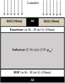
Figure 2. Schematic diagram of a heterojunction photovoltaic (PV) solar cell structure.
All simulations of the heterojunction photovoltaic solar cell were carried out under standard operating conditions: AM1.5 spectrum, light intensity of 0.1 W/cm², and a temperature of 300 K.
4. Results and Discussion
The electrical performance of a heterojunction photovoltaic (PV) solar cell strongly depends on the thickness of the different layers that compose it.
In this section, we analyze the influence of the emitter layer thickness on the cell’s performance using the TCAD-SILVACO Atlas simulator. The two key parameters of the p+-doped hydrogenated amorphous silicon emitter layer (p+-a-Si:H), namely its thickness and its dopant concentration, are studied as the main variables.
Initially, the emitter layer thickness was varied from 2 nm to 20 nm for different base thickness values, while keeping the dopant concentration and the other physical parameters of the device constant. The study focused on the evolution of the following key parameters: the open-circuit voltage VOC, the fill factor (FF), the short-circuit current density JSC, and the overall conversion efficiency.
4.1. PV Parameters as a Function of FSF Thickness
The heavily doped front surface field (FSF) layer [(p+)-a-Si:H] plays a major role in the performance of heterojunction solar cells .
With the aim of optimizing this layer, we conducted a study on the variation of its thickness in this section. We simulated several heterojunction solar cells (with different crystalline silicon (c-Si) base thicknesses) for various emitter thicknesses ranging from 2 to 20 nm.
i) Cell Efficiency (η) as a Function of FSF Thickness
As shown in Figure 3, increasing the thickness of the front emitter layer (FSF) from 2 nm to 5 nm significantly improves the efficiency, reaching a maximum of 23.5% at 5 nm. This improvement is attributed to better light absorption, particularly at longer wavelengths, which is characteristic of hydrogenated amorphous silicon (p+-a-Si:H).
However, beyond this optimal thickness, further increases lead to two detrimental effects: a growing opacity of the layer, which limits light penetration into the deeper layers, and an increase in minority carrier recombination, which reduces the extractable current. This phenomenon is explained by the reduction in diffusion length L, which is directly related to carrier lifetime τ and diffusion coefficient D according to the following relation:
L=D.τ (11)
This equation highlights the importance of minimizing recombination mechanisms in the emitter layer to maintain high efficiency, especially when its thickness increases.
Thus, excessive thickness not only reduces the collection current but also results in significant optical losses due to internal absorption . Optimizing the emitter layer thickness is therefore essential to balance efficient light absorption and minimal recombination losses, ensuring maximum cell efficiency. The results of this study are presented in Figure 3.
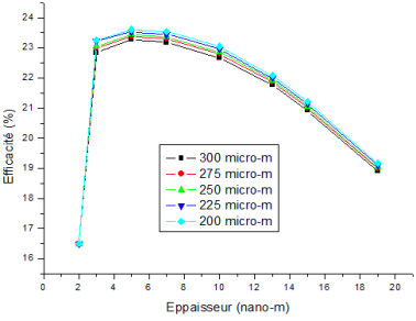
Figure 3. Impact of varying FSF layer thickness on cell efficiency.
ii) Short-Circuit Current Density (JSC) as a Function of FSF Thickness
Figure 4 shows the evolution of the short-circuit current density JSC as a function of the emitter layer thickness (p+-a-Si:H) in a heterojunction photovoltaic cell. For thicknesses between 2 nm and 5 nm, the current density increases rapidly. This improvement is attributed to enhanced material quality of the hydrogenated amorphous silicon layer, which becomes more homogeneous and less prone to electronic defects as its thickness increases. This better quality promotes the efficient generation and collection of photogenerated carriers.
Within this thickness range, the series resistance progressively decreases due to the reduction of contact barriers and the improved conductivity of the emitter layer. At the same time, the parallel resistance increases, indicating a reduction in leakage currents associated with parasitic recombination. These combined effects contribute to more efficient current extraction.
Beyond 5 nm, the current density continues to increase more slowly until it reaches a plateau. This trend is explained by the increasing optical opacity of the emitter layer, which absorbs a growing fraction of the incident light without significantly contributing to useful carrier generation. Moreover, greater thickness increases the transit time of minority carriers, raising the probability of recombination before reaching the ohmic contacts.
The optimal thickness, identified around 5 nm, therefore represents a compromise between the optical absorption capacity of the layer, its electronic quality, and the management of series and parallel resistances. Excessive thickness beyond this threshold induces optical and electronic losses that gradually degrade cell performance. The results of this study are presented in Figure 4.
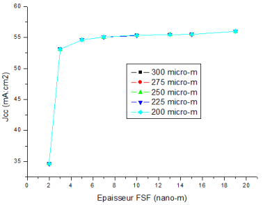
Figure 4. Impact of varying FSF layer thickness on cell current density.
iii) Open-Circuit Voltage (VOC) as a Function of FSF Thickness
Figure 5 shows a progressive decrease in the open-circuit voltage VOC as the thickness of the emitter layer (p+-a-Si:H) increases. This degradation in VOC is mainly due to intensified recombination mechanisms, particularly at the interfaces. Increasing the FSF thickness raises the defect density within the layer and at the interfaces, promoting minority carrier recombination especially holes from the (n)-c-Si substrate via interfacial trap states.
When the thickness becomes excessive, bulk recombination dominates, causing a significant loss of open-circuit voltage. In contrast, a thinner, well-passivated emitter layer effectively limits both surface and bulk recombination, resulting in an increase in VOC. Optimizing this layer’s thickness is therefore essential to maintain a high open-circuit voltage, a key parameter in the overall performance of photovoltaic cells. The results of this study are presented in Figure 5.
Figure 5. Impact of varying FSF layer thickness on cell open circuit voltage.
iv) Fill Factor (FF) as a Function of FSF Thickness
The fill factor (FF) progressively decreases as the thickness of the emitter layer (FSF) increases (Figure 6). This degradation is primarily due to the increase in recombination within the p+-a-Si:H layer, which directly influences the internal resistivity of the FSF and, consequently, the ohmic losses. Excessive thickness thus impairs the cell’s ability to maintain an optimal current-voltage curve shape, which is essential for achieving a good fill factor.
The combined analysis of the evolution of the fill factor, the open-circuit voltage VOC, the short-circuit current density  JSC, and the efficiency shows that a thickness of approximately 5 nm provides the optimal balance for maximizing overall cell performance.
Simulation results demonstrate that the front emitter layer (FSF) thickness plays a decisive role in the performance of heterojunction solar cells. A thin layer (around 5 nm) simultaneously optimizes the short-circuit current density. JSC, the open-circuit voltage VOC, and the fill factor (FF), leading to a maximum efficiency of 24%. At this thickness, the layer offers an ideal compromise between optical absorption, low opacity, effective interface defect passivation, and minimized bulk and surface recombination.
In contrast, increasing the thickness beyond this optimal value raises the layer’s resistivity, enhances recombination, degrades VOC and FF, and limits potential performance gains. This result underlines the importance of emitter layer thickness optimization to ensure efficient and stable cell operation. The results of this study are presented in Figure 6.
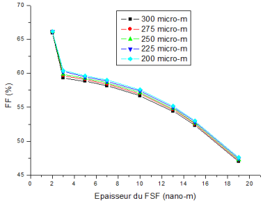
Figure 6. Impact of varying FSF layer thickness on cell form factor.
The variation in FSF thickness has a significant influence on the overall photoelectric characteristics of the cell.
4.2. PV Parameters as a Function of FSF Doping
The emitter layer (a-Si:H) plays a particularly critical role in the performance of photovoltaic solar cells. It is essential to evaluate the effect of its doping concentration on the overall cell performance. For this purpose, the doping concentration Na was varied within the range of 1.1017cm-3 to 1.1020cm-3. For the other layers c-Si (absorbing layer) and a-Si:H (rear layer) the doping concentrations Nd were set to 5.1015 to 1.1020cm-3, respectively.
i) Effect of FSF (Front Surface Field) Emitter Layer Doping
The upper p+-n junction, formed between the p+-doped hydrogenated amorphous silicon emitter layer (p+-a-Si:H) and the n-type crystalline silicon absorbing layer (n-c-Si), induces an electric field within the space charge region, establishing a potential barrier favorable to charge carrier separation .
This section focuses on optimizing the performance parameters of heterojunction solar cells, specifically the conversion efficiency, short-circuit current density JSC, open-circuit voltage VOC, and fill factor (FF) as a function of the doping level of the emitter layer (p+-a-Si:H), under constant temperature conditions of 300 K.
ii) Effect of Emitter Doping on Cell Efficiency (η)
A low photovoltaic cell efficiency is observed (Figure 7) when the doping concentration of the emitter layer (p+-a-Si:H) is relatively low, around 1017 cm⁻³. As the doping level increases, the efficiency improves in a nearly linear manner.
This improvement is explained by the evolution of the Fermi level positions. At low doping levels, the difference between the Fermi levels of the two materials forming the junction (p+-a-Si:H/n-c-Si) is larger, which limits the internal electric field and reduces the efficiency of charge carrier separation and collection.
Conversely, increasing the dopant concentration in the emitter layer reduces this gap, thereby strengthening the electric field at the junction and improving charge separation. This configuration promotes better collection of photogenerated carriers, resulting in higher cell efficiency. The effect of emitter layer doping on the efficiency of heterojunction photovoltaic solar cell is illustrated in Figure 7.
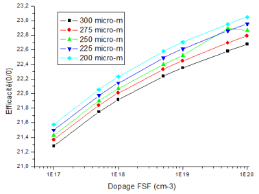
Figure 7. Evolution of cell efficiency as a function of FSF layer doping.
iii) Effect of Emitter Doping on Short-Circuit Current Density (JSC)
The analysis of Figure 8 reveals an increase in the short-circuit current density JSC with the rise in the emitter layer doping level. This improvement is mainly attributed to the modification of the electric field profile at the p+-n junction.
When the doping concentration in the p+-a-Si:H layer increases, the electric field induced in the space charge region becomes more intense due to the higher concentration of fixed charges on both sides of the junction (in the p+ emitter and the n-type base). This enhanced field lowers the effective potential barrier that minority carriers must overcome.
Under these conditions, photogenerated carriers in the n-c-Si base are more efficiently driven towards the junction, which significantly improves their collection. Thus, the current density increases with doping, reflecting improved charge transport and reduced recombination losses in the junction region. The effect of emitter layer doping on the current density of heterojunction photovoltaic solar cell is illustrated in Figure 8.
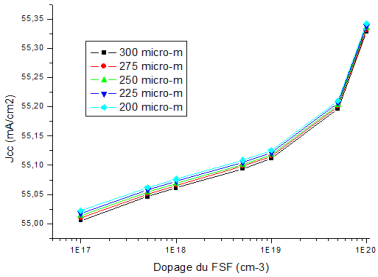
Figure 8. Evolution of cell current density as a function of FSF layer doping.
iv) Effect of Emitter Doping on Open-Circuit Voltage (VOC)
The curves in Figure 9 show a positive correlation between the doping level of the emitter layer (p+-a-Si:H) and the open-circuit voltage VOC. As the dopant concentration increases, a progressive improvement in VOC is observed.
This trend is explained by the fact that higher doping levels in the emitter lead to a reduction in the diffusion potential, which enhances the separation of the quasi-Fermi levels. This configuration allows for more effective separation of photogenerated carriers and limits recombination at the junction, contributing to the increase in open-circuit voltage. The effect of emitter layer doping on the open circuit voltage of the heterojunction photovoltaic solar cell is illustrated in Figure 9.
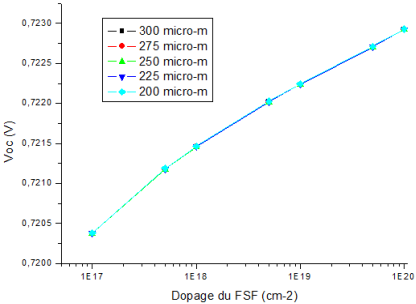
Figure 9. Evolution of cell open-circuit voltage as a function of FSF layer doping.
v) Effect of Emitter Doping on the Fill Factor (FF)
Increasing the doping concentration in the emitter layer (p+-a-Si:H) results in a nearly linear improvement in the fill factor (FF) (Figure 10). This evolution is explained by the reduction in emitter resistivity, which is directly related to the increased doping.
Indeed, electrical resistivity is inversely proportional to the concentration of free carriers, so higher doping improves the conductivity of the emitter layer. This enhanced conduction reduces internal ohmic losses, optimizes charge transport, and thus contributes to improving the fill factor.
The study highlights the strategic importance of the doping level of the emitter layer (p+-a-Si:H) in optimizing the performance of heterojunction solar cells. A gradual increase in dopant concentration simultaneously improves the open-circuit voltage VOC, the short-circuit current density  JSC, and the fill factor (FF), leading to a significant enhancement in overall conversion efficiency.
These improvements can be explained by several combined mechanisms:
1) The reduction in emitter layer resistivity, which improves electrical conduction and reduces ohmic losses.
2) The strengthening of the electric field at the junction, which promotes charge separation and collection.
3) The decrease in diffusion potential, which contributes to the increase in VOC.
As a result, well-optimized doping maximizes the electrical performance of the cell while maintaining a balance between passivation, conduction, and charge transport. However, it should be noted that excessively high doping levels may, beyond a certain threshold, induce additional recombination or structural disorder, justifying the need for precise optimization.
Simulation results confirm that the thickness of the front emitter layer (FSF) plays a crucial role in the performance of heterojunction solar cells. A thin layer (around 5 nm) simultaneously optimizes the short-circuit current density  JSC, the open-circuit voltage VOC, and the fill factor (FF), leading to a maximum efficiency of 23.5%. At this thickness, the layer provides an excellent balance between optical absorption, low opacity, effective interface defect passivation, and minimized bulk and surface recombination.
Conversely, increasing the thickness beyond this value raises the layer’s resistivity, promotes recombination, degrades VOC and FF, and limits performance improvement.
Recent studies by Khairuddin et al. (2023) demonstrated that excessive emitter layer thickness increases recombination, thereby reducing efficiency, while well-calibrated doping optimizes charge transport without compromising passivation . Additionally, Zhang et al. (2022) achieved an efficiency of 26.45% by simultaneously optimizing the thickness and doping of the a-Si:H(n) emitter layer, which improved both the fill factor and open-circuit voltage . The effect of emitter layer doping on the form factor of the heterojunction photovoltaic solar cell is illustrated in Figure 10.
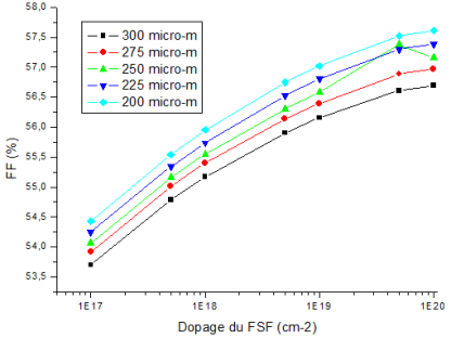
Figure 10. Evolution of cell form factor as a function of FSF layer doping.
Varying the FSF doping significantly influences the overall photoelectric characteristics of the cell.
4.3. Effect of the Band Gap Energy on Photovoltaic Parameters
The band gap energy  Eg is a key parameter influencing the performance of photovoltaic solar cells . Studies by Steiner et al. (2023) and Taguchi et al. (2005) have shown that an appropriately selected  Eg value maximizes charge separation while minimizing thermal losses.
In this study, we analyzed the impact of different  Eg values, considering various emitter layer thicknesses to evaluate their combined effect on the key performance parameters of the cell, namely: open-circuit voltage VOC, short-circuit current density  JSC, fill factor (FF), and conversion efficiency.
i) Effect of Band gap Energy on Efficiency (η)
Figure 11 illustrates the combined impact of the band gap energy  Eg and the thickness of the emitter layer on the efficiency of photovoltaic solar cells. The results show that cells with a larger band gap in the emitter layer are generally less efficient. This decrease is due to the fact that photons with energy lower than the band gap are not absorbed, reducing the amount of light converted into electrical energy.
Conversely, cells with a smaller band gap absorb a greater portion of the solar spectrum but incur significant thermal losses due to the excess energy of photons beyond the absorption threshold. There is thus an optimal band gap that maximizes efficiency by balancing effective absorption and minimizing thermal losses.
Additionally, a regular and significant increase in efficiency is observed for all cells, regardless of the band gap, as the FSF thickness increases up to approximately 3 nm, beyond which efficiency stabilizes. However, when the thickness exceeds this value, cells with a large band gap experience a marked performance drop, while those with a smaller band gap remain relatively stable, with minimal sensitivity to thickness variations.
These observations suggest that cells with larger band gaps are more sensitive to thickness variations, possibly due to a reduction in recombination probability facilitated by a more direct transition of charges between the conduction and valence bands. This configuration makes these cells less effective at higher thicknesses due to reduced absorption and weakened charge transport.
Nevertheless, we achieved an efficiency of 24% for a heterojunction photovoltaic solar cell with a front emitter gap of less than 1.7 eV and a thickness between 5 and 7 nm. The evolution of the efficiency of a heterojunction photovoltaic solar cell with different emitting layer band gap values as a function of the front layer thickness are shown in Figure 11.
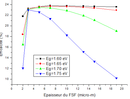
Figure 11. Evolution of Efficiency as a Function of FSF Thickness for Different Band gap Energies.
ii) Effect of Band gap Energy on Current Density (JSC)
The results show that reducing the band gap energy (Eg) leads to an increase in the short-circuit current density (JSC) when the emitter layer thickness (FSF) is between 2 nm and 3 nm (Figure 12). In this range, cells with a smaller Eg exhibit broader absorption capacity, which enhances carrier generation and consequently results in higher current.
Beyond a 3 nm thickness, the current density becomes nearly constant regardless of the band gap, suggesting a saturation of absorption and generation mechanisms. However, for a cell with a band gap of 1.75 eV, a rapid drop in JSC is observed starting from a thickness of 13 nm, indicating a degradation of carrier collection beyond this limit.
Generally, increasing the band gap reduces the number of absorbed photons since only those with energy higher than the band gap can be converted, leading to a decrease in current density. Conversely, a lower band gap allows absorption of a larger portion of the solar spectrum, increasing carrier generation and the current produced by the cell. The evolution of the current density of a heterojunction photovoltaic solar cell with different emitting layer band gap values as a function of the front layer thickness are shown in Figure 12.
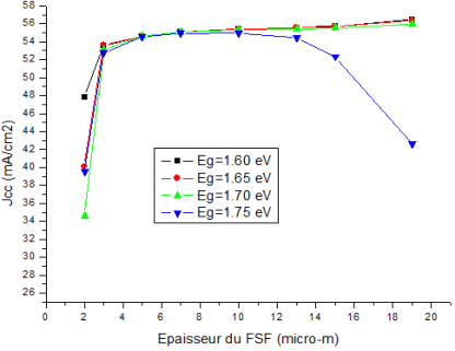
Figure 12. Evolution of the current density as a function of FSF thickness for different band gap energies.
iii) Effect of Band gap Energy on Open-Circuit Voltage (VOC)
The open-circuit voltage (VOC) is strongly affected by variations in band gap energy (Eg). It varies positively with decreasing bandgap energy when the FSF layer thickness is between 2 nm and 3 nm. With a thickness greater than 3 nm, cells with a small band gap maintain a stable. VOC, while those with medium and large band gaps show a decrease.
The  VOC depends directly on the minimum energy required to excite an electron into the conduction band. A large band gap in the FSF layer reduces the number of absorbed photons, theoretically increasing. VOC. However, excessive band gap combined with increased FSF thickness significantly limits photon absorption, restricting carrier generation and paradoxically leading to a reduction in VOC.
Optimizing both the band gap width and emitter layer thickness is essential to maximize this parameter. The open circuit voltage evolution of a heterojunction photovoltaic solar cell with different emitter layer band gap values as a function of the front layer thickness are shown in Figure 13.
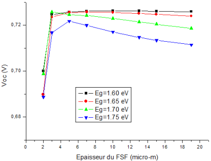
Figure 13. Open-circuit voltage variation as a function of FSF thickness for different band gap energies.
iv) Effect of Band gap Energy on Fill Factor (FF)
Like other photovoltaic parameters, the fill factor (FF) is also influenced by the band gap energy (Figure 14). For emitter layer thicknesses between 2 nm and 3 nm, a sharp and uniform decrease in FF is observed regardless of the band gap value.
Beyond 3 nm, behavior diverges depending on the band gap: cells with a low band gap show FF stabilization, while those with a large band gap experience a significant decline. This degradation is attributed to two combined factors:
1) A more challenging energy barrier, hindering carrier transport;
2) Increased diffusion length, associated with reduced emitter layer conductivity, resulting in higher resistivity and thus a lower FF.
The observed trends align with findings from other similar studies , confirming the strong link between band gap energy, material conductivity, and photovoltaic cell performance.
The study highlights the critical role of the emitter layer band gap energy (Eg) in the operation and optimization of heterojunction solar cells. The results show that overall cell performance is highly sensitive to the band gap value, particularly in configurations with thin emitter layers (between 2 nm and 3 nm).
Reducing the band gap enables better solar spectrum absorption, increasing JSC but potentially leading to higher thermal losses and reduced stability beyond certain thicknesses. Conversely, an excessively high Eg restricts photon absorption, decreasing JSC and potentially affecting FF due to increased resistivity and challenges in efficient carrier extraction.
Regarding open-circuit voltage (VOC), a moderate Eg value combined with an optimized emitter layer thickness maximizes this parameter. The fill factor tends to be relatively stable at low Eg but significantly degrades at high Eg and large thicknesses, indicating increased electronic transport limitations.
During our simulations, we initially used indium tin oxide (ITO) as the front layer, following conventional heterojunction solar cell structures. However, simulations with reduced ITO thickness did not yield convergent or exploitable results. To overcome these numerical difficulties and continue the structural parameter analysis, we temporarily substituted ITO with a silicon dioxide (SiO2) layer, which stabilized the simulations and provided coherent results in terms of carrier profiles and overall performance.
It should be emphasized that this substitution is not intended for real-world fabrication since SiO2 is an insulating material and does not fulfill the necessary conduction functions. Our approach is exploratory, aimed at analyzing the cell's sensitivity to front layer thickness and identifying underlying physical trends. Further detailed modeling with appropriate TCO parameters or experimental validation will be required in future work. The evolution of the form factor of a heterojunction photovoltaic solar cell with different emitting layer band gap values as a function of the front layer thickness are shown in Figure 14.
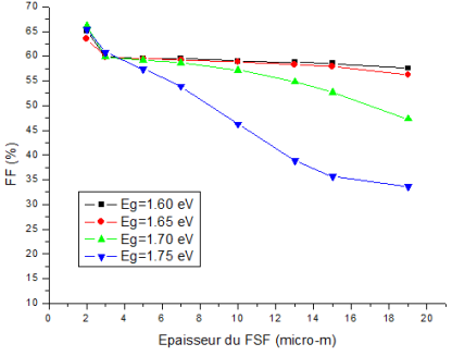
Figure 14. Form factor evolution as a function of FSF thickness for different bandgap energies.
The results observed in Section 4.3 are consistent with those of Sehyeon Kim un, Park Hyeongsik et al , confirming the close link between the band gap energy and the electrical properties of photovoltaic cells.
5. Conclusion
The comprehensive analysis of the results highlights that the optimal performance of a heterojunction solar cell relies on a delicate balance between the emitter layer (FSF) thickness, doping level, and band gap energy (Eg). Each of these parameters interdependently influences the fundamental operating mechanisms of the cell, including photon absorption, charge separation and collection, recombination phenomena, and electrical resistivity.
1) A layer that is too thin limits absorption and passivation quality, while excessive thickness promotes recombination and optical losses.
2) Insufficient doping results in a weak electric field and poor charge collection, whereas excessive doping may increase recombination or alter material structure.
3) The band gap energy governs the balance between solar spectrum absorption and thermal losses, with maximum efficiency achieved in a moderate Eg range combined with optimized geometry.
These complex interactions demonstrate that designing a high-efficiency cell requires simultaneous and carefully calibrated optimization of the FSF layer's optoelectronic properties. The observed trends in this study are consistent with literature data and confirm the importance of integrated sizing to achieve an effective balance between generation, transport, and carrier extraction.
Simultaneous optimization of the emitter layer's thickness, doping, and band gap energy is essential to ensure maximum photovoltaic performance. This conclusion aligns with findings by Jain et al. (2021) , who emphasized the need for integrated adjustment of these three parameters to limit recombination losses and enhance energy conversion.
Abbreviations

PV

Photovoltaic

SHJ

Silicon Heterojunction

FSF

Front Surface Field

a-Si

Hhydrogenated Amorphous Silicon

BSF

Back Surface Field

Si

Silicon

VOC

Open-Circuit Voltage

JSC

Short-Circuit Current Density

FF

Fill Factor

η

Efficiency

SiO₂

Silicon Dioxide

RP

Parallel Resistance

RS

Series Resistance

I

Output Current

Iph

Photocurrent

ID1

Generation/Recombination Current in the Space Charge Region (SCR)

ID2

Diffusion Current in the Quasi-Neutral Regions

Ip

Resistive Loss Current

J01

Saturation Current Density of Diode D1 Related to Carrier Diffusion in the Quasi-Neutral Regions of the Base and Emitter

J02

Saturation Current Density of Diode D2 Related to the Generation/Recombination Current in the Space Charge Region

RS et RP

Series and Shunt Resistances, Respectively

n1,2

Ideality Factors of Diodes

k

Boltzmann Constant

q

Elementary Charge

T

Temperature (K)

V

Voltage Across the Cell (V)

VT

Thermal Voltage

T

Absolute Temperature

IS

Saturation Current

P(W)

Power Measured at the PV Cell Terminals

U(V)

Voltage Across the PV Cell Terminals

I(A)

Current Measured at the PV Cell Terminals

Pmax W

Maximum Power Delivered by the PV Cell

Vmax, Imax

Voltage and Current at the Maximum Power Point

Pinc

Incident Light Power

S

Cell Surface Area

SRH

Shockley-Read-Hall

Eg

Band Gap

χ

Electron Affinity

μn

Electron Mobility

μp

Hole Mobility

Nc

Effective Density of States in Conduction Band

Nv

Effective Density of States in Valence Band

ε

Relative Permittivity

NGA, NGD

Gaussian-Shaped Acceptor (Donor) States Density

NTA, NTD

Conduction Band Tail Acceptor (Donor) States Density

EGA, EGD

Gaussian Peak Energy

WGA, WGD

Gaussian Distribution Width

WTA, WTD

Band tail Distribution Width

σn

Electron Capture Cross-Section

σp

Hole Capture Cross-Section

L

Diffusion Length

τ

Life Time

D

Diffusion Coefficient

Nd

Doping Concentrations

Author Contributions
Mamadou Lamine Samb: Conceptualization, Data curation, Formal Analysis, Investigation, Methodology, Project administration, Software, Supervision, Validation, Visualization, Writing – original draft, Writing – review & editing
Aly Toure: Conceptualization, Data curation, Formal Analysis, Investigation, Methodology, Software, Validation, Writing – review & editing
Moussa Toure: Conceptualization, Data curation, Formal Analysis, Investigation, Methodology, Resources, Software, Supervision, Validation, Visualization, Writing – original draft, Writing – review & editing
Mouhamadou Sam: Conceptualization, Data curation, Formal Analysis, Investigation, Methodology, Software, Validation, Writing – review & editing
Fatma Sow: Conceptualization, Formal Analysis, Investigation, Methodology, Software, Validation, Writing – review & editing
Ahmed Mohamed Yahya: Conceptualization, Data curation, Formal Analysis, Funding acquisition, Investigation, Methodology, Project administration, Resources, Software, Supervision, Validation, Visualization, Writing – original draft, Writing – review & editing
Conflicts of Interest
The authors declare no conflicts of interest.
References
[1] Jan Haschke et al. (2018). Silicon heterojunction solar cells: Recent technological development and practical aspects – from lab to industry. Solar Energy Materials and Solar Cells, 187, 140–153.
[2] Nandhini Kullampalayam Murugaiyan, Kumar Chandrasekaran, Premkumar Manoharan, & Bizuwork Derebew. Leveraging opposition-based learning for solar photovoltaic model parameter estimation with exponential distribution optimization algorithm. Scientific Reports, 14, Article number: 528(2024).
[3] B. S. S. Ganesh Pardhu, & Venkata Reddy Kota. A novel HRMO-AOA approach for a grid integrated wind-solar PV system with a 5-level NPC inverter. Results in Engineering, 23(2024), 102582.
[4] Mohamed Saleck Heyine. Performance analysis of a 50 MWp grid-connected photovoltaic solar power plant of SOMELEC. Doctoral Thesis, University of Nouakchott (2023).
[5] Djicknoum Diouf. Silicon heterojunction photovoltaic cells with interdigitated back contact structure. Doctoral Thesis, Université Paris Sud 11(2010).
[6] M. N. Kateb, S. Tobbeche, & A. Merazga. Influence of μc-Si:H tunnel recombination junction on the performance of a-Si:H/μc-Si:H tandem solar cell. Optik, 139(2017), 152-165.
[7] Venkanna Kanneboina, Ramakrishna Madaka, & Pratima Agarwal. High open circuit voltage c-Si/a-Si:H heterojunction solar cells: Influence of hydrogen plasma treatment studied by spectroscopic ellipsometry. Solar Energy, 166(2018), 255-266.
[8] Chedia Aliani, Monem Krichen, & Abdelaziz Zouari. Effect of the front metal work function on the performance of Si:H(n+)/a-Si:H(i)/c-Si(p) heterojunction solar cells. Journal of Computational Electronics, 18(2019), 576–583.
[9] Souad Tobbeche & Mohamed Nadjib Kateb. Simulation and optimization of silicon solar cell back surface field. Materials Science, 21(4) (2015), 575-581.
[10] K. Bendjebbara, W. L. Rahal, D. Rached, & S. Bahlouli. Numerical analysis of metal-semiconductor junctions ITO/p-a-Si:H and n-c-Si/Al on silicon heterojunction solar cells. Optik, 212(2020), 164741.
[11] Duy Phong Pham, Sangho Kim, Sehyeon Kim, Sunhwa Lee, Anh Huy Tuan Le, Jinjoo Park, & Junsin Yi. Ultra-thin stack of n-type hydrogenated microcrystalline silicon and silicon oxide front contact layer for rear-emitter silicon heterojunction solar cells. Materials Science in Semiconductor Processing, 96(2019), 1-7.
[12] T. F. Schulze, C. Leendertz, N. Mingirulli, L. Korte, & B. Rech. Impact of Fermi-level dependent defect equilibration on Voc of amorphous/crystalline silicon heterojunction solar cells. Energy Procedia, 8(2011), 282-287.
[13] N. S. Khairuddin et al. The effects of thickness and doping concentration on the solar efficiency of GaNp-Si based solar cells. Chalcogenide Letters, 20(12) (2023), 629-637.
[14] Y. Zhang et al. Emitter layer optimization in heterojunction bifacial silicon solar cells. Journal of Semiconductors, 43(12) (2022), 122701.
[15] M. A. Steiner et al. Modeling and design of III-V heterojunction solar cells for enhanced performance. National Renewable Energy Laboratory (2023).
[16] M. Taguchi et al. Obtaining a higher Voc in HIT cells. Progress in Photovoltaics: Research and Applications, 13(6) (2005), 481-488.
[17] Sehyeon Kim, Hyeongsik Park, & Duy Phong Pham. Design of front emitter layer for improving efficiency in silicon heterojunction solar cells via numerical calculations. Optik, 235(2021), 166580.
[18] A. Jain et al. Design of front emitter layer for improving efficiency in silicon heterojunction solar cells. Optik, 241(2021), 166942.
Cite This Article
  • APA Style

    Toure, A., Toure, M., Samb, M. L., Sam, M., Sow, F., et al. (2025). Front Surface Field (FSF) Layer Thickness Engineering in Heterojunction Solar Cells: Efficiency Optimization Through Predictive SILVACO-TCAD Simulation. Advances in Materials, 14(3), 65-79. https://doi.org/10.11648/j.am.20251403.11

    Copy | Download

    ACS Style

    Toure, A.; Toure, M.; Samb, M. L.; Sam, M.; Sow, F., et al. Front Surface Field (FSF) Layer Thickness Engineering in Heterojunction Solar Cells: Efficiency Optimization Through Predictive SILVACO-TCAD Simulation. Adv. Mater. 2025, 14(3), 65-79. doi: 10.11648/j.am.20251403.11

    Copy | Download

    AMA Style

    Toure A, Toure M, Samb ML, Sam M, Sow F, et al. Front Surface Field (FSF) Layer Thickness Engineering in Heterojunction Solar Cells: Efficiency Optimization Through Predictive SILVACO-TCAD Simulation. Adv Mater. 2025;14(3):65-79. doi: 10.11648/j.am.20251403.11

    Copy | Download

  • @article{10.11648/j.am.20251403.11,
      author = {Aly Toure and Moussa Toure and Mamadou Lamine Samb and Mouhamadou Sam and Fatma Sow and Ahmed Mohamed Yahya},
      title = {Front Surface Field (FSF) Layer Thickness Engineering in Heterojunction Solar Cells: Efficiency Optimization Through Predictive SILVACO-TCAD Simulation
    },
      journal = {Advances in Materials},
      volume = {14},
      number = {3},
      pages = {65-79},
      doi = {10.11648/j.am.20251403.11},
      url = {https://doi.org/10.11648/j.am.20251403.11},
      eprint = {https://article.sciencepublishinggroup.com/pdf/10.11648.j.am.20251403.11},
      abstract = {This study focuses on optimizing the thickness, doping, and bandgap energy of the Front Surface Field (FSF) layer in silicon heterojunction (SHJ) solar cells using predictive simulation with SILVACO-TCAD. SHJ solar cells are known for their high efficiency, low-cost manufacturing, and low-temperature fabrication processes. The FSF layer, typically composed of p+-doped hydrogenated amorphous silicon (a-Si:H), plays a pivotal role in determining cell performance. Key Methodology: The research employs the TCAD-SILVACO Atlas simulation software to model SHJ solar cells and analyze the influence of FSF layer parameters on photovoltaic performance, particularly the open-circuit voltage (VOC), short-circuit current density (JSC), fill factor (FF), and overall efficiency (η). The simulation integrates the Poisson and continuity equations, Boltzmann statistics, and models for Auger and Shockley-Read-Hall (SRH) recombination. Major Findings: FSF Thickness: Optimal efficiency (~23.5%) is achieved with an FSF thickness around 5 nm. Increasing the thickness beyond this value leads to reduced VOC and FF due to enhanced recombination and increased resistivity. Doping Concentration: Higher doping levels in the FSF layer strengthen the electric field at the junction, improving carrier separation and collection. However, excessive doping can cause additional recombination, emphasizing the need for balanced optimization. Bandgap Energy: A lower bandgap enhances photon absorption but increases thermal losses, while a higher bandgap limits absorption but can theoretically improve VOC. An optimal bandgap value around 1.7 eV, combined with a 5-7 nm thickness, was identified for peak efficiency. Simulation Stability: The study temporarily replaced the conventional indium tin oxide (ITO) front layer with silicon dioxide (SiO2) for simulation stability. This substitution was for numerical purposes only and is not applicable in real-world fabrication. The research highlights that achieving high-efficiency heterojunction solar cells requires precise, simultaneous optimization of the FSF layer's thickness, doping concentration, and bandgap energy. The study confirms that a careful balance of these parameters minimizes recombination losses, optimizes charge transport, and enhances photovoltaic performance. Future work should involve further experimental validation and the integration of more realistic front contact materials such as transparent conductive oxides (TCOs).},
     year = {2025}
    }
    

    Copy | Download

  • TY  - JOUR
    T1  - Front Surface Field (FSF) Layer Thickness Engineering in Heterojunction Solar Cells: Efficiency Optimization Through Predictive SILVACO-TCAD Simulation
    
    AU  - Aly Toure
    AU  - Moussa Toure
    AU  - Mamadou Lamine Samb
    AU  - Mouhamadou Sam
    AU  - Fatma Sow
    AU  - Ahmed Mohamed Yahya
    Y1  - 2025/07/28
    PY  - 2025
    N1  - https://doi.org/10.11648/j.am.20251403.11
    DO  - 10.11648/j.am.20251403.11
    T2  - Advances in Materials
    JF  - Advances in Materials
    JO  - Advances in Materials
    SP  - 65
    EP  - 79
    PB  - Science Publishing Group
    SN  - 2327-252X
    UR  - https://doi.org/10.11648/j.am.20251403.11
    AB  - This study focuses on optimizing the thickness, doping, and bandgap energy of the Front Surface Field (FSF) layer in silicon heterojunction (SHJ) solar cells using predictive simulation with SILVACO-TCAD. SHJ solar cells are known for their high efficiency, low-cost manufacturing, and low-temperature fabrication processes. The FSF layer, typically composed of p+-doped hydrogenated amorphous silicon (a-Si:H), plays a pivotal role in determining cell performance. Key Methodology: The research employs the TCAD-SILVACO Atlas simulation software to model SHJ solar cells and analyze the influence of FSF layer parameters on photovoltaic performance, particularly the open-circuit voltage (VOC), short-circuit current density (JSC), fill factor (FF), and overall efficiency (η). The simulation integrates the Poisson and continuity equations, Boltzmann statistics, and models for Auger and Shockley-Read-Hall (SRH) recombination. Major Findings: FSF Thickness: Optimal efficiency (~23.5%) is achieved with an FSF thickness around 5 nm. Increasing the thickness beyond this value leads to reduced VOC and FF due to enhanced recombination and increased resistivity. Doping Concentration: Higher doping levels in the FSF layer strengthen the electric field at the junction, improving carrier separation and collection. However, excessive doping can cause additional recombination, emphasizing the need for balanced optimization. Bandgap Energy: A lower bandgap enhances photon absorption but increases thermal losses, while a higher bandgap limits absorption but can theoretically improve VOC. An optimal bandgap value around 1.7 eV, combined with a 5-7 nm thickness, was identified for peak efficiency. Simulation Stability: The study temporarily replaced the conventional indium tin oxide (ITO) front layer with silicon dioxide (SiO2) for simulation stability. This substitution was for numerical purposes only and is not applicable in real-world fabrication. The research highlights that achieving high-efficiency heterojunction solar cells requires precise, simultaneous optimization of the FSF layer's thickness, doping concentration, and bandgap energy. The study confirms that a careful balance of these parameters minimizes recombination losses, optimizes charge transport, and enhances photovoltaic performance. Future work should involve further experimental validation and the integration of more realistic front contact materials such as transparent conductive oxides (TCOs).
    VL  - 14
    IS  - 3
    ER  - 

    Copy | Download

Author Information